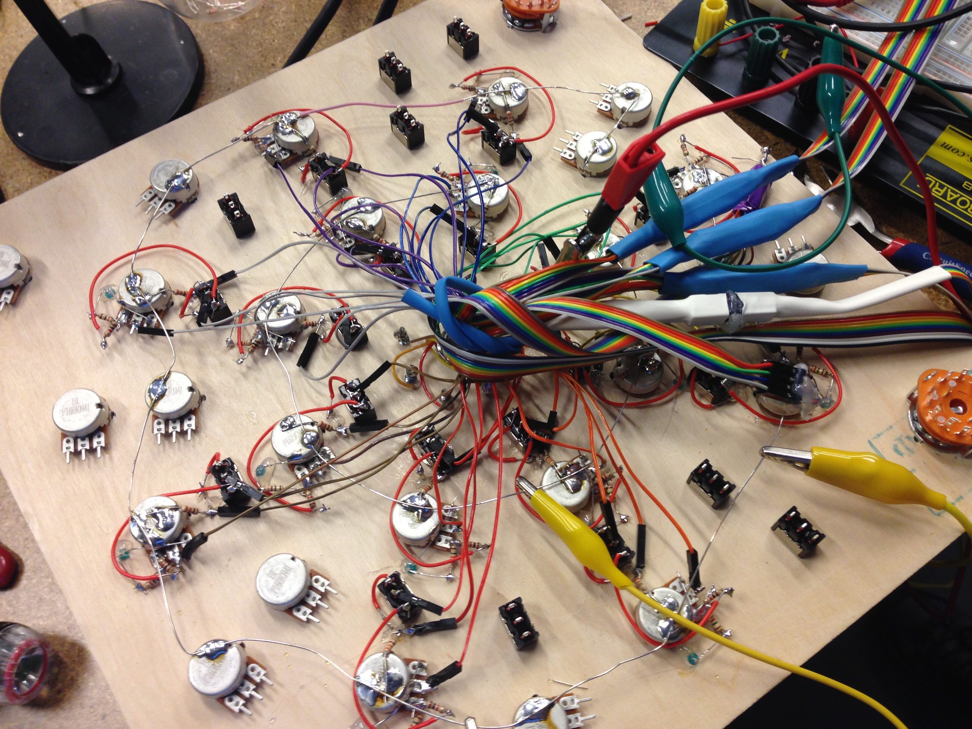
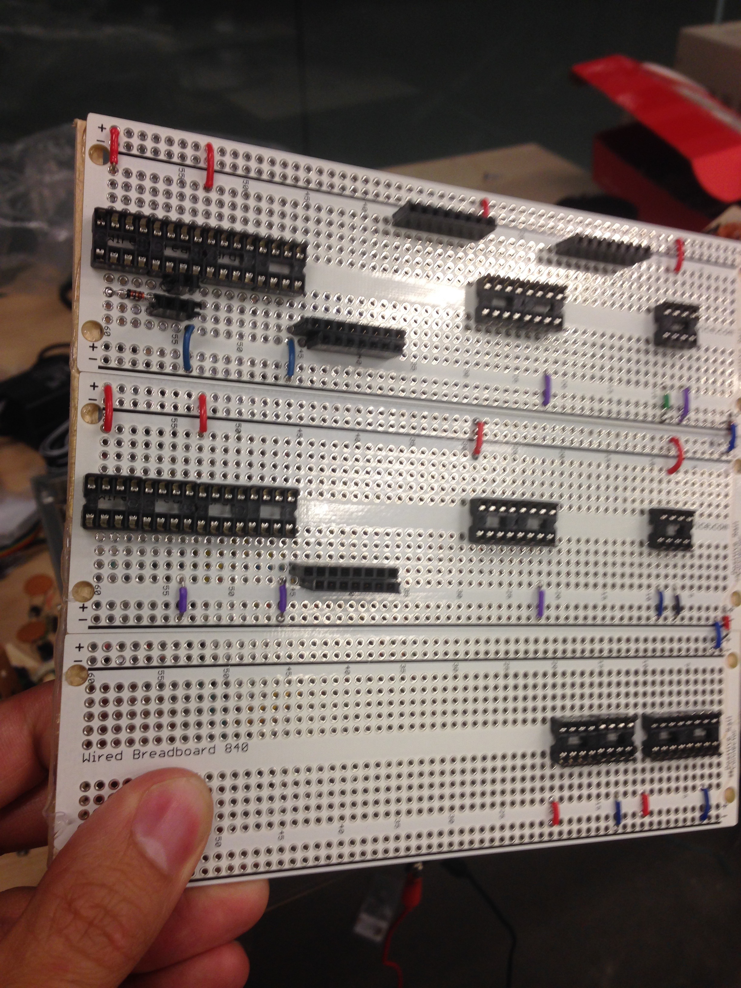
Analogue Revolutions is handbuilt using integrated circuits (ICs) and passive components, there’s no programmable (PIC) chips and thus no computer is involved. This point was important to me back in 2014.
Analogue Revolutions was completed May 2015 in the Physical Media Lab (PML) at the Perry and Marty Granoff Center for the Creative Arts, Brown University, USA. The instrument developed through my teaching of ‘Circuit Bending and Hardware Hacking as Musical and Artistic Expression’, I’m grateful to Chira Delsesto for providing PML access for the class in 2014, and for allowing me access in the first half of 2015 to complete the project.
This project is inspired by, draws upon, and would not have been possible had I not discovered the work of Nic Collins in 2005. Anyone interested in this stuff should check out Collins, N. (2009). Handmade electronic music: The art of hardware hacking (2nd ed.). New York: Routledge. Alternatively, download the early-version that is available direct from Nic’s website (link here).

What does it do?
Analogue Revolutions features two variable step-sequencers arranged in concentric circles. Each sequencer outputs to an individual voltage controlled oscillator and can also be used to rhythmically slice external analogue inputs using vactrols (AKA resistive opto-isolators). Each sequencer is driven by either of two independent clocks, which are dynamically variable in speed but have toggles to choose 1) a range of slow to fast pulses keeping things within the bounds of rhythm and groove, or 2) very fast to audio-rate pulses, which facilitate various timbral possibilities (more on that later). Sequence lengths are variable in the range of one to eight steps via rotary selector switches. The button in the centre resets both counters simultaneously, this is important because if both sequencers are driven by the same clock they will count at the same time, but will only trigger the same step at the same time if identical step-lengths are selected for each sequencer and if the counters have been recently reset/synchronized.
The output of each step is fed via a toggle switch to either a rotary potentiometer or a light dependent resistor (LDR). When the potentiometer is selected a light emitting diode (LED) provides visual feedback whenever the step is triggered (no LED in LDR mode to avoid interference). Each LDR is configured as a voltage divider using an additional fixed resistor to pass useful voltage only in the presence of direct artificial light, this is because 1) I like to perform in dimly-lit spaces with a torch 2) in most situations, except perhaps performing outdoors in direct/extreme Australian sunshine, the toggle can be used as a mute switch for each individual step.
Overview: two independent clocks with switchable ranges drive two independent variable-length sequencers, which can listen to either clock (switchable). Each sequencer outputs a variable voltage, this is permanently routed both to a voltage controlled oscillator and the LED of a vactrol for rhythmic slicing of external inputs.
Voltage Controlled Oscillator (VCO)
The potentiometers or LDRs control the pitch of each step and there’s also a master control that dramatically increases the pitch-range. Each VCO has an individual potentiometer to control the volume level of its output. A dual-stage distortion circuit is available in parallel to the direct signal, this also has an individual potentiometer to control the volume level, and the screw-heads in the centre of the instrument can be used as touch-points for tactile interplay. Both ‘clean’ and ‘distorted’ outputs are summed together and fed into a potentiometer that controls the overall volume level of each sequencer. An additional potentiometer for each VCO also feeds in-built speakers, useful for mobile performances. Sound can either be localized in the instrument or outputted to a PA and there is ample flexibility to celebrate the sonic differences offered by direct outputs versus inbuilt amplification. Although both VCOs are mono, each VCO outputs on two mono jack sockets and pseudo-stereo panning has been implemented using vactrols so the output appears to jump from one side of the stereo spectrum to the other. Quadrophonic performances are possible due to a total of four outputs (two for each VCO).
Overall, when clocked at sub-audio rate the VCO produces convincing grooves and has melodic possibilities via the pitch controls for each step and the overall pitch-range control. It’s also fun running the clocks at audio rate, which pushes into timbre/frequency modulation territory. Adding in the two distortion circuits (which are deliberately configured quite differently) brings wild/grungy tones and the touch-points add a lot of character.
Another interesting point is the interaction with the inbuilt amplifier; sending signal to this brings fun timbral change and various inconsistencies (to both the direct outputs and the internally amplified signals). I guess this is really a ‘fault’, I may have missed a capacitor or two for isolation at the amplifier’s input, and/or this should probably be buffered, but I find the ‘fault’ quite performable and have come to enjoy it.
There’s an essential tie-down resistor on the input of both the voltage controlled oscillators (VCO), but I have switches that break this connection and cause a fair amount of noisy chaos, the switches themselves are also directly wired to the VCO input, so are touch-sensitive and can be performed quite expressively (especially when also touching the screw-heads that are routed to the distortion chip).
Rhythmic Slicing of External Inputs Using Vectrols
The output of each sequencer (before the VCO) is also routed to an internal LED, which illuminates to varying degrees of brightness in direct proportion to the voltage output of each step (as controlled via the potentiometers or LDRs). This LED is isolated from other light sources, and is physically coupled to an LDR and then wrapped in heat-shrink and tape to create a homemade vactrol. Inserting this LDR into the path of an incoming signal (via input and output sockets) means that external inputs can be sliced up (turned off/on) by the sequencer and the volume of each step is directly proportional to the voltage output of each step (as controlled via the potentiometers or LDRs), though I used a tie-down resistor to make this more effective.
Overall, in rhythmic slicing mode Analogue Revolutions can be used to slice two external inputs simultaneously. Although I’ve played some gigs using vectrol slicing I don’t currently have any decent documentation, so check out this video by Leafcutter John, which uses the same technique and makes clear what is going on.
Rough Technical Details
- Two inputs of a CMOS 40106 Hex Schmitt Trigger Inverter are used to drive the two clocks, each has a switchable capacitor to control the range and a potentiometer for dynamic speed control (feedback resistor). Each clock also drives two light emitting diodes (LEDs) which are coupled to light dependent resistors that feed the left and right audio output sockets to create panning effects when using the instrument for voltage controlled synthesis. (One LED is inverted using another input of the CMOS 40106 Inverter);
- Two CMOS 4017 decade counters are used to to create the variable-step sequencers;
- Two CD4046B Phase-Locked Loops are used for voltage controlled synthesis (these are the infamous chips used in touch-tone telephones);
- The 4049 Hex Inverter chip is used with a variety of feedback resistors and capacitors to create interesting distortion effects;
- Two LM386 chips are used to power the two internal speakers.
What is special about the Hex Schmitt Trigger and can you explain how it works? See here.
Documentation
In 2017 I used a ton of different technologies, including Analogue Revolutions, to perform two duo concerts with Vanessa Tomlinson, see TOMLIN|FERGUS — I’m using VCO mode only, no vactrol slicing (yet).
Working on documentation. More soon!
Build Process